
IconXdesign.com Icon and Foam Layout
Additional information about how the Icons and Foam are laid out in the program.
Note: when we are referring to “First row” of Icons this is the first in the simply supported span. All icons above the roof connection remain at 1 every 8 sf (above the Green dashed line).
Icon Layout OPTIMIZATION
The program initially lays out Icon connectors in the standard pattern, approximately 1 every 8 square feet. In the program, you can increase the number of Icons in each row to increase the strength and stiffness of the panel. As the number of Icons in the row increases, the program will place them in the optimal sheet of foam. This helps keep a standardized layout. Always remember that engineering judgment should always be used. The program’s recommended layout may not work with your design, but Icons are permitted to move laterally in the row.
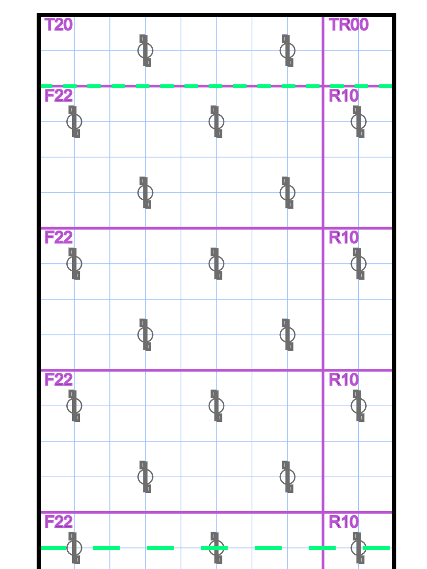
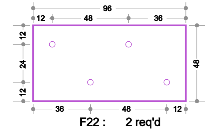
Picture 1. Default Layout (F22 and R10 Read Foam Naming Convention below )
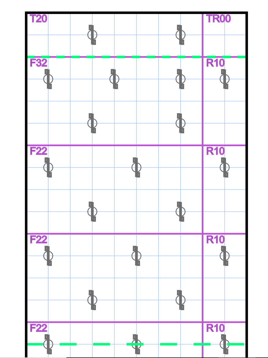
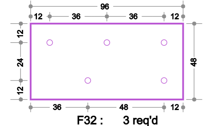
Picture 2. Extra Icon in top row (F32 and R10)
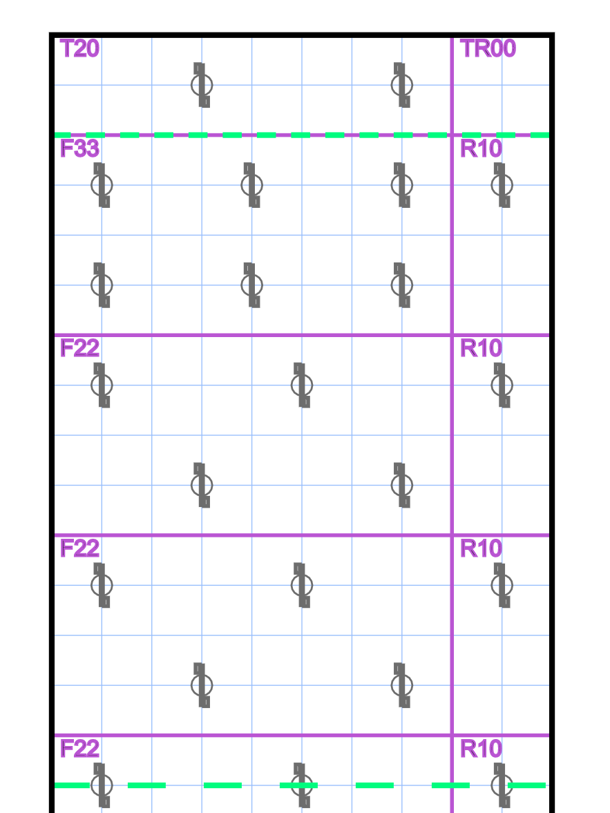
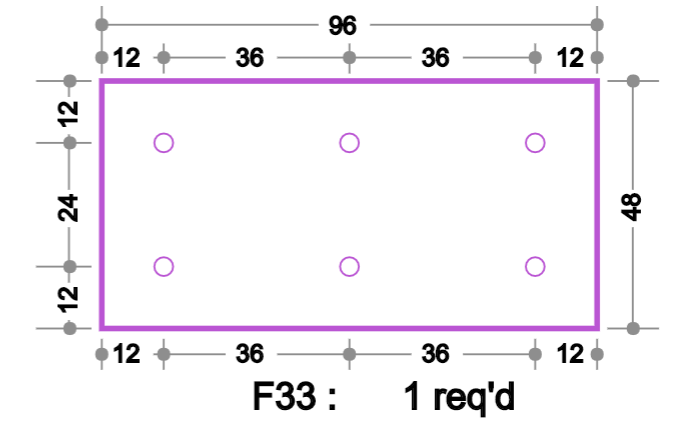
Picture 3. Extra icon in 1st and 2nd row (F33 and R10)
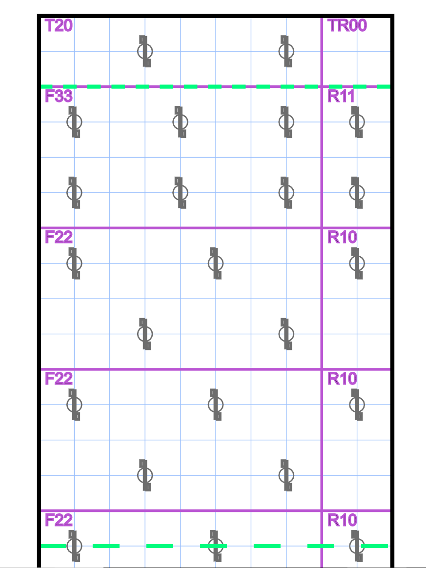
Picture 4. Extra icon in 1st row and two additional in 2nd row (F33 and R11)
Read Foam Naming Convention below
Foam sheet OPTIMIZATION
The distance between the first row of Icons and the start of the span is controlled by the program. By shifting the position of the first row we are able to optimize the number of full 8 x 4 foam sheets. The effects of moving the first row is minimal for the overall strength of the panel. This allows us to save you money in both material waste and number of hours cutting foam.
Click to enlarge
Foam Naming Convention
We developed a new naming convention for the foam sheets. Each name has 2 parts. The first part is the Type which describes the location and if it is unique to the panel.
Type: F = Full T = Top R = Right M = Middle B = Bottom
All Full and Mid sheets are uncut 8' x 4'. They are identical to all similarly named sheets, so if you have 100 on the project they can be used in any panel that calls for them. The remaining Top Right and Bottom Sheets all are cut specifically for each panel and MUST be used in the panel they are designed for.
The Second part of the name identifies the number of Icons in the top row and the bottom row. For example the typical F22 is a full sheet of foam with two Icons in the top row and 2 in the bottom row. This is what 80 percent of your project is likely to be. If there were instead 3 Icons in the top row you would have a F32.
You may also see the Flip designation on the main drawing. A flipped sheet of foam is cut to match it's name. For example if the top half of the panel calls for three standard R21 and the bottom half calls for three Flip R21 sheets then you cut six R21 sheets. When placing the foam in however you will flip the bottom half of the panels sheets upside down so that you get the correct number of Icons in each row.
Is the OPTIMIZATION perfect?
No. Icon layout in the software program is a great starting point for those who have never done a project with us. If you are working on more complex shapes, block outs or have imbedment interference then the layout will need to be adjusted using engineering judgement. The simple rule of thumb is to keep the icon that is interfering in the same row but to move it laterally to the next closest location. After shifting icons in your project review the spacing to make sure there are no large sections without icons to minimize delamination forces.
The optimization will attempt to layout your project in as few unique foam layouts as possible. This will sometimes leave you with unevenly spaced icons. If you prefer to have even spacing of icon across the width of the panel go for it just remember to keep the same number of Icon in each row.